Sunday, February 19, 2012
Fire Fighting Programming
My biggest priority while working on the fire fighting robot was to program the Vex microcontroller. In this code, you can see that I tried to keep my functions simple and very orderly. The simplest way I knew learned to program were to use a lot of if statements and while loops to ensure that the robot either continues to act on a function or to do it one time. The unique feature I included is that I use the same search room function throughout the entire search pattern. This was able to be determined because every room I entered with the robot, I was closer towards a wall to the left of the robot, thus allows for me to use the same 180 degree turn to face the outside again. I also used the same search room function since all i needed the robot to do was to scan room once.
Fire Fighting Final Design
Here is a picture of the final design of Pat-J JR. This is an top angled front view of the robot as it faces the camera with the fan mechanism.
Here is an angled side view so that perspective of the mechanism to the drive is more noticeable.
Here is a side view of the robot. Here we can get a much more clear picture of what the robot looks like at the base. It may not be visible in this picture, but there are two small wheels on the inside which also are covered with electric tape.
Here is the diagram of what the competition looked like. The circle at the bottom of the picture is the home circle where competitors must start from that position. The robot was not required to be completely inside the circle.
Fire Fighting Production
Here, you can see that my partner JJ and myself used the optical shaft encoders on the front wheels along the outer side walls of the chassis. In addition to the modification, there is also electric tape around the wheels. The purpose of the electric tape is to decrease the friction from the total amount of grip, at the same time balance out the slippage and dragging of the wheels to a more consistent state. This allowed the encoders to read more accurate values and also in being able to make more accurate turning.
Here is a picture of two Infrared Sensors used to detect the flame. Inside the electric tape is a 20k resistor which helped control the reading the IR sensor is collecting from a light source and allowing the programmer to use a more accurate and reliable reading to let the computer know that there is an actual flame inside. The values we kept as standard fluctuated around 289 and 320. Anything higher than these values would imply that there is a flame nearby for the sensors to detect.
This is the sonar sensor we used on Pat-J Jr. The sonar is ideally used to help navigate around tight spaces such as hallways and navigating out of the rooms. The efficiency of using the sonar dramatically improves the response as well as the ability to leave a room. The sonar pings sounds to a distance and receives the signal again and is then able to determine the distance away (inches) by the judging the time in which the waves of signals are released and then collected.
This is a VEX bumper switch. The switch was not used particularly in the navigating aspect of the robot. Rather, the button was used to prevent the robot from running prematurely once the microcontroller was turned on. Rather, the robot would have to wait until the button was pressed in order to start the program.
Thursday, February 16, 2012
Interfacing a Microcontroller: LDR
Here is a quick demonstration of me using an LDR sensor to let the microcontroller know when to send power signals to the appropriate outputs. Here, if the light sensor (gray sensor on the left) receives light, the red bulb will be lit. However, when I cover the light, the green bulb will light up and the red one will shut off. Using the DB-9 cable, I was able to use the picaxe programming tool to allow the microcontroller to accept values from the LDR and transmitting those values into data to be used to activate or deactivate a specific function of a mechanism or light.
Wednesday, February 15, 2012
Interfacing a Microcontroller
Here is a quick demonstration of how i used a Christmas tree light bulb and programmed into the picaxe brain. The program written allowed the bulb to turn on and off every half a second.
Introduction to Microcontrollers
This exercise took a while to figure out. But i finally got used to programming the microcontroller. Here, we can see that the light bulb is not lit for the time being.
Continuing from the picture above, we can see that the red LED light is lit. I programmed the microcontroller to turn on and off the LED every 1 second in a blinking manner.
This picture shows that I integrated a push button to activate the microcontroller. When the button is pressed, the light will turn on, stay on for 1 second and turn off.
Here is a quick demonstration of how the button pressed affected the LED to at output 1 of the microcontroller.
Transistor Switching
In this first picture, we can see that the LED has a power source to that barely allows the LED to light. Much like a probe, large black wire with no connectivity will either send ground or power to the transistor which will either brighten the LED or turn it off.
Here, you can see that the large black wire is connected to the positive terminal of the board. As a result, the LED light up much brighter than it originally was. This helps to indicate that the transistor used was a PNP transistor.
And finally, once the same black wire was connected to ground, there was not complete circuity and the LED did not turn on at all.
While using the NPN transistor, the LED was not lit because of the button, which regulated the power signals to transit over to the transistor. Since there is no power to begin with, a ground signal could not be completed to light the LED.
However, once the button was pressed, the ground signal completed the circuit which allwed the LED to light up.
Friday, February 10, 2012
Switches and Relays
In this exercise, I learned how to use a single throw switch to turn on the LED as well as using a double throw switch located at the top of the picture. Here, when both switches are giving the same output, the LED will like up. However if the switches are feeding opposite power signals, the LED will shut off. This simulation is a lot like how some hallway lights work where there are two switches at the ends of a hallway.
From this exercise, the same principle applies, but this time, a relay is used. The relay works by switching the ground and positive signals to oscillate between two points of a circuit board. To demonstrate, the button on the left is left alone which indicates that the ground is going to the relay and thus completing the circuit for the green LED. And the red indicates that there is an incomplete circuity and thus no light will show.
After hitting the switch tho, we can clearly see that the positive signal is transferred to the relay completing the circuit for the red bulb, and sending power to the relay to the green which makes it an incomplete circuit.
Friday, February 3, 2012
VEX Programming (Autonomous)
Here is a picture of my VEX robot at the starting position. The robot needed to navigate itself autonomously through the small maze and arrive at a designated square at the end of the self navigation arena. marked by electric tape.
The robot was very far from the space needed to succeed. I was approximately 14 inches away from the goal.
Monday, January 30, 2012
Building a Logic Probe
Constructing this logic probe was much harder than doing it on the breadboard. Mostly because I had to worry about it being a "final" product and cannot be undone once the soldering joints were attached. In addition to the difficulty, it was hard to remember from time to time which resistors and transistors connected where.
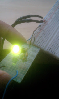
Once my logic probe was completed, i was able to test it. Here, we can see that my logic probe is receiving power from the 5 volt power supply. The LED is now properly lit with the prob not touching anything.
When I connect the probe to a positive terminal, the LED luminated much brighter. This indicates that the probe is connected to a power source directly and can see that this connectivity to the probe is clearly positive.
Here, we can clearly see that once the probe is connected to a ground, the LED is turned off. This technique is very helpful when trying to determine if a circuit is positive or ground.
Schematics, Ohm's Law and Potentiometers
Learning about ohm's law, we can see in this picture that the greater the ohms a resistor inflicts, the less luminescence a bulb will become. Due to the lack of voltage running through the wires from the power or ground. The smallest resistor produced the brightest light.
In this picture, there wasn't a full demonstration available, but the potentiometer was able to adjust for the amount of current to flow through. Turning the knob allowed more or restricted more energy to pass through the potentiometer.
Multi Meter and Breadboards
In this exercise, I needed to be able to identify the kind of resistors used in our project. To be able to read the level of ohms a resistor carries is by identifying the colors and reading them correctly. The first and second colors indicated are numerical digits and the third line is the factor of 10 in which the two digits are multiplied by. At the end of the reading, there is a faintly gold strip on the right to indicate that i was reading it in the right order of coloring. In this one, there is a red, red, red, resistor. First red is 2, second is 2, and third color is a multiplier of 100, thus producing 2200 ohms of resistance.
In addition to learning about resistors, multimeters are a great way to test conductivities, resistance as well as the amount of volts a particular hardware or power source produces. In these 3 pictures with the multimeter, I demonstrated how one would use a multimeter to find out how much power or ohms a hardware may contain.
In this picture, I used the 5 volt power supply we made earlier in the winter semester and demonstrated how to use a breadboard and light up the LED using a small resistor.
Thursday, January 26, 2012
Hack a ToyProject Winter 2012
Here is a picture of a claw I have been working on. There is a light at the palm of the claw, however it was sadly burnt out during a test. The claw is simply a claw and its only purpose is to open and close.
In addition to the use of hacking this toy, the main purpose of its use is to be able to synchronize the claw manually and to be used for a "grabber" mechanism for the RoboSub Team. I believe that the motors will eventually need to be upgraded, but for the sake of time and further debugging to perfect the motion of the claw, this will have to be on hold.
My objective for hacking this toy is to attach the claw to the Picaxe 08M2 microcontroller and allow the user to manually control the claw with the use of a single pole single throw button and a 5 volt relay. The ideal motion of the claws command is to remain off until the button is pushed. However, the amount of current the claw requires is causing issuse for the relay to work with the claw at the same time. To resolve this issue, i have used a secondary power supply providing 3 volts of power to the motor directly (with a 4001 Diode). From here, a code has been written so that the claw will open indefinitely and will only oscillate with the relay switch once the button is pressed and held.
A future goal will be to install a more heavy duty motor and allow for a fully stopped motor on the claw and to integrate a "open" and "close" function independently so that the claw will be at the full control of the user.
Wednesday, January 11, 2012
Intro to Soldering and Heatshrinking
Here, we took a 5-volt LG-phone charger and cut the end of the plug. Following the cut, I stripped the first layer rubber around 2 wires. Afterwards, two more wires were exposed which also needed to be spliced. Once the positive and negative copper fibers were exposed, I soldered the two joints with a stripped wire to another join with a single strand to allow for the testing of conductivity and connectivity of the soldered wires. After, shrink wrapping the wires allowed for a smooth finish with no exposed wires except for the ends.
Although there should have been 4 soldered joints with shrink wrapping around the exposed wires, I was running out of time, so only 3 joints were made. Adding flux to the exposed wires definitely made the connectivity of the joints much simpler. Thank you Flux!
Here is a shot of my first ever soldered breadboard. The ugliest soldering joint was obviously my first attempt. Conic shaped, smooth, and brightly silver colored are the preferred indications of correct soldering.
Here is another image with a more clear shot of what happened. Same breadboard, just different angle.
Subscribe to:
Posts (Atom)