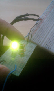
 Constructing this logic probe was much harder than doing it on the breadboard. Mostly because I had to worry about it being a "final" product and cannot be undone once the soldering joints were attached. In addition to the difficulty, it was hard to remember from time to time which resistors and transistors connected where.
  Once my logic probe was completed, i was able to test it. Here, we can see that my logic probe is receiving power from the 5 volt power supply. The LED is now properly lit with the prob not touching anything.
When I connect the probe to a positive terminal, the LED luminated much brighter. This indicates that the probe is connected to a power source directly and can see that this connectivity to the probe is clearly positive.

Here, we can clearly see that once the probe is connected to a ground, the LED is turned off. This technique is very helpful when trying to determine if a circuit is positive or ground.
No comments:
Post a Comment