Monday, January 30, 2012
Building a Logic Probe
Constructing this logic probe was much harder than doing it on the breadboard. Mostly because I had to worry about it being a "final" product and cannot be undone once the soldering joints were attached. In addition to the difficulty, it was hard to remember from time to time which resistors and transistors connected where.
Once my logic probe was completed, i was able to test it. Here, we can see that my logic probe is receiving power from the 5 volt power supply. The LED is now properly lit with the prob not touching anything.
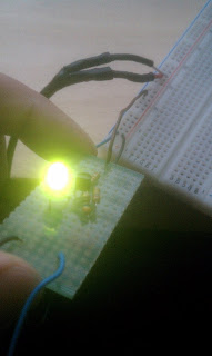
When I connect the probe to a positive terminal, the LED luminated much brighter. This indicates that the probe is connected to a power source directly and can see that this connectivity to the probe is clearly positive.
Here, we can clearly see that once the probe is connected to a ground, the LED is turned off. This technique is very helpful when trying to determine if a circuit is positive or ground.
Schematics, Ohm's Law and Potentiometers
Learning about ohm's law, we can see in this picture that the greater the ohms a resistor inflicts, the less luminescence a bulb will become. Due to the lack of voltage running through the wires from the power or ground. The smallest resistor produced the brightest light.
In this picture, there wasn't a full demonstration available, but the potentiometer was able to adjust for the amount of current to flow through. Turning the knob allowed more or restricted more energy to pass through the potentiometer.
Multi Meter and Breadboards
In this exercise, I needed to be able to identify the kind of resistors used in our project. To be able to read the level of ohms a resistor carries is by identifying the colors and reading them correctly. The first and second colors indicated are numerical digits and the third line is the factor of 10 in which the two digits are multiplied by. At the end of the reading, there is a faintly gold strip on the right to indicate that i was reading it in the right order of coloring. In this one, there is a red, red, red, resistor. First red is 2, second is 2, and third color is a multiplier of 100, thus producing 2200 ohms of resistance.
In addition to learning about resistors, multimeters are a great way to test conductivities, resistance as well as the amount of volts a particular hardware or power source produces. In these 3 pictures with the multimeter, I demonstrated how one would use a multimeter to find out how much power or ohms a hardware may contain.
In this picture, I used the 5 volt power supply we made earlier in the winter semester and demonstrated how to use a breadboard and light up the LED using a small resistor.
Thursday, January 26, 2012
Hack a ToyProject Winter 2012
Here is a picture of a claw I have been working on. There is a light at the palm of the claw, however it was sadly burnt out during a test. The claw is simply a claw and its only purpose is to open and close.
In addition to the use of hacking this toy, the main purpose of its use is to be able to synchronize the claw manually and to be used for a "grabber" mechanism for the RoboSub Team. I believe that the motors will eventually need to be upgraded, but for the sake of time and further debugging to perfect the motion of the claw, this will have to be on hold.
My objective for hacking this toy is to attach the claw to the Picaxe 08M2 microcontroller and allow the user to manually control the claw with the use of a single pole single throw button and a 5 volt relay. The ideal motion of the claws command is to remain off until the button is pushed. However, the amount of current the claw requires is causing issuse for the relay to work with the claw at the same time. To resolve this issue, i have used a secondary power supply providing 3 volts of power to the motor directly (with a 4001 Diode). From here, a code has been written so that the claw will open indefinitely and will only oscillate with the relay switch once the button is pressed and held.
A future goal will be to install a more heavy duty motor and allow for a fully stopped motor on the claw and to integrate a "open" and "close" function independently so that the claw will be at the full control of the user.
Wednesday, January 11, 2012
Intro to Soldering and Heatshrinking
Here, we took a 5-volt LG-phone charger and cut the end of the plug. Following the cut, I stripped the first layer rubber around 2 wires. Afterwards, two more wires were exposed which also needed to be spliced. Once the positive and negative copper fibers were exposed, I soldered the two joints with a stripped wire to another join with a single strand to allow for the testing of conductivity and connectivity of the soldered wires. After, shrink wrapping the wires allowed for a smooth finish with no exposed wires except for the ends.
Although there should have been 4 soldered joints with shrink wrapping around the exposed wires, I was running out of time, so only 3 joints were made. Adding flux to the exposed wires definitely made the connectivity of the joints much simpler. Thank you Flux!
Here is a shot of my first ever soldered breadboard. The ugliest soldering joint was obviously my first attempt. Conic shaped, smooth, and brightly silver colored are the preferred indications of correct soldering.
Here is another image with a more clear shot of what happened. Same breadboard, just different angle.
Subscribe to:
Posts (Atom)